F’ Math Component Tutorial
Table of Contents
- 1. Introduction
- 2. The MathOp Type
- 3. The MathOp and MathResult Ports
- 4. The MathSender Component
- 5. The MathReceiver Component
- 6. Updating the Ref Deployment
- 7. Running the Ref Deployment
- 8. Conclusion
1. Introduction
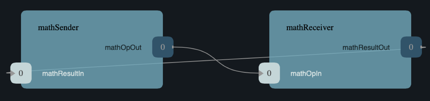
This tutorial shows how to develop, test, and deploy a simple topology consisting of two components:
-
MathSender: A component that receives commands and forwards work toMathReceiver. -
MathReceiver: A component that carries out arithmetic operations and returns the results toMathSender.
See the diagram below.
What is covered: The tutorial covers the following concepts:
-
Using the FPP modeling language to specify the types and ports used by the components.
-
Using the F Prime build system to build the types and ports.
-
Developing the
MathSendercomponent: Specifying the component, building the component, completing the C++ component implementation, and writing component unit tests. -
Developing the
MathReceivercomponent. -
Adding the new components and connections to the F Prime
Refapplication. -
Using the F Prime Ground Data System (GDS) to run the updated
Refapplication.
Prerequisites: This tutorial assumes the following:
-
Basic knowledge of Unix: How to navigate in a shell and execute programs.
-
Basic knowledge of git: How to create a branch.
-
Basic knowledge of C++, including class declarations, inheritance, and virtual functions.
If you have not yet installed F Prime on your system, do so now.
Follow the installation guide at INSTALL.md
in the F Prime git repository.
You may also wish to work through the Getting Started tutorial at
docs/GettingStarted/Tutorial.md.
F´ Version: This tutorial is designed to work with release v3.0.0.
Working on this tutorial will modify some files under version control in the F Prime git repository. Therefore it is a good idea to do this work on a new branch. For example:
git checkout -b math-tutorial v3.0.0
If you wish, you can save your work by committing to this branch.
2. The MathOp Type
In F Prime, a type definition defines a kind of data that you can pass between components or use in commands and telemetry.
For this tutorial, we need one type definition.
It defines an enumeration called MathOp, which
represents a mathematical operation.
We will add the specification for the MathOp type to the
Ref topology.
We will do this in three stages:
-
Construct the FPP model.
-
Add the model to the project.
-
Build the model.
2.1. Construct the FPP Model
Create the MathTypes directory:
Go to the directory Ref at the top-level of the
F Prime repository and run mkdir MathTypes.
This step creates a new directory Ref/MathTypes.
This directory will contain our new type.
Create the FPP model file:
Now go into the directory Ref/MathTypes.
In that directory, create a file MathTypes.fpp with the following contents:
module Ref {

  @ A math operation
  enum MathOp {
    ADD @< Addition
    SUB @< Subtraction
    MUL @< Multiplication
    DIV @< Division
  }

}
You can do this by typing, or by copy-paste.
This file defines an enumeration or enum with enumerated constants ADD,
SUB, MUL, and DIV.
These four constants represent the operations of addition, subtraction,
multiplication, and division.
The enum also defines a type MathOp; the enumerated constants are the values
of this type.
For more information on enums, see The FPP User’s
Guide.
The enum MathTypes resides in an FPP module Ref.
An FPP module is like a C++ namespace: it encloses several definitions, each of which is qualified with the name of the module. For more information on FPP modules, see The FPP User’s Guide.
The text following a symbol @ or @< is called an annotation.
These annotations are carried through the parsing and become comments in the
generated code.
For more information, see The FPP User’s
Guide.
2.2. Add the Model to the Project
Create Ref/MathTypes/CMakeLists.txt:
Create a file Ref/MathTypes/CMakeLists.txt with the following contents:
set(SOURCE_FILES
  "${CMAKE_CURRENT_LIST_DIR}/MathTypes.fpp"
)

register_fprime_module()
This code will tell the build system how to build the FPP model.
Update Ref/CMakeLists.txt:
Now we need to add the new directory to the Ref project.
To do that, open the file Ref/CMakeLists.txt.
This file should already exist; it was put there by the developers
of the Ref topology.
In this file, you should see several lines starting with add_fprime_subdirectory.
Immediately after the last of those lines, add the following new line:
add_fprime_subdirectory("${CMAKE_CURRENT_LIST_DIR}/MathTypes/")
2.3. Build the Model
Run the build: Do the following:
-
Go to the directory
Ref/MathTypes. -
If you have not already run
fprime-util generate, then do so now. -
Run the command
fprime-util build.
The output should indicate that the model built without any errors. If not, try to identify and correct what is wrong, either by deciphering the error output, or by going over the steps again. If you get stuck, you can look at the reference implementation.
Inspect the generated code:
Now go to the directory Ref/build-fprime-automatic-native/Ref/MathTypes
(you may want to use pushd, or do this in a separate shell,
so you don’t lose your current working directory).
The directory build-fprime-automatic-native is where all the
generated code lives for the “automatic native” build of the Ref
project.
Within that directory is a directory tree that mirrors the project
structure.
In particular, Ref/build-fprime-automatic-native/Ref/MathTypes
contains the generated code for Ref/MathTypes.
Run ls.
You should see something like this:
CMakeFiles            MathOpEnumAc.cpp      MathOpEnumAi.xml.prev cmake_install.cmake
Makefile              MathOpEnumAc.hpp      autocoder
The files MathOpEnumAc.hpp and
MathOpEnumAc.cpp are the auto-generated C++ files
corresponding to the MathOp enum.
You may wish to study the file MathOpEnumAc.hpp.
This file gives the interface to the C++ class Ref::MathOp.
All enum types have a similar auto-generated class
interface.
2.4. Reference Implementation
A reference implementation for this section is available at
docs/Tutorials/MathComponent/MathTypes.
To build this implementation from a clean repository,
do the following:
-
Go to the
Refdirectory. -
Run
cp -R ../docs/Tutorials/MathComponent/MathTypes . -
Update
Ref/CMakeLists.txtas stated above. -
Follow the steps for building the model.
If you have modified the repo, revise the steps accordingly.
For example, switch git branches, use git stash to stash
your changes, or move MathTypes to another directory such
as MathTypes-saved.
3. The MathOp and MathResult Ports
A port is the endpoint of a connection between two components. A port definition is like a function signature; it defines the type of the data carried on a port.
For this tutorial, we need two port definitions:
-
MathOpfor sending an arithmetic operation request fromMathSendertoMathReceiver. -
MathResultfor sending the result of an arithmetic operation fromMathReceivertoMathSender.
We follow the same three steps as in the previous section.
3.1. Construct the FPP Model
Create the MathPorts directory:
Go to the directory Ref at the top-level of the
F Prime repository and run mkdir MathPorts.
This directory will contain our new ports.
Create the FPP model file:
Now go into the directory Ref/MathPorts.
Create a file MathPorts.fpp with the following contents:
module Ref {

  @ Port for requesting an operation on two numbers
  port MathOp(
               val1: F32 @< The first operand
               op: MathOp @< The operation
               val2: F32 @< The second operand
             )

  @ Port for returning the result of a math operation
  port MathResult(
                   result: F32 @< the result of the operation
                 )

}
This file defines the ports MathOp and MathResult.
MathOp has three formal parameters: a first operand, an
operation, and a second operand.
The operands have type F32, which represents a 32-bit
floating-point number.
The operation has type MathOp, which is the enum type
we defined in the previous section.
MathResult has a single formal parameter, the value of type F32
returned as the result of the operation.
For more information about port definitions, see The FPP User’s Guide.
3.2. Add the Model to the Project
Add add the model
Ref/MathPorts/MathPorts.fpp to the Ref project.
Carry out the steps in the
previous section, after
substituting MathPorts for MathTypes.
3.3. Build the Model
Carry out the steps in the
previous section,
in directory MathPorts instead of MathTypes.
The generated code will go in
Ref/build-fprime-automatic-native/Ref/MathPorts.
For port definitions, the names of the auto-generated C++
files end in PortAc.hpp and PortAc.cpp.
You can look at this code if you wish.
However, the auto-generated C++ port files are used
by the autocoded component implementations (described below);
you won’t ever program directly against their interfaces.
3.4. Reference Implementation
A reference implementation for this section is available at
docs/Tutorials/MathComponent/MathPorts.
To build this implementation, follow the steps
described for MathTypes.
4. The MathSender Component
Now we can build and test the MathSender component.
There are five steps:
- Construct the FPP model.
- Add the model to the project.
- Build the stub implementation.
- Complete the implementation.
- Write and run unit tests.
4.1. Construct the FPP Model
Create the MathSender directory:
Go to the directory Ref at the top-level of the
F Prime repository.
Run mkdir MathSender to create a directory for the new component.
Create the FPP model file:
Now go into the directory Ref/MathSender.
Create a file MathSender.fpp with the following contents:
module Ref {

  @ Component for sending a math operation
  active component MathSender {

    # ----------------------------------------------------------------------
    # General ports
    # ----------------------------------------------------------------------

    @ Port for sending the operation request
    output port mathOpOut: MathOp

    @ Port for receiving the result
    async input port mathResultIn: MathResult

    # ----------------------------------------------------------------------
    # Special ports
    # ----------------------------------------------------------------------

    @ Command receive port
    command recv port cmdIn

    @ Command registration port
    command reg port cmdRegOut

    @ Command response port
    command resp port cmdResponseOut

    @ Event port
    event port eventOut

    @ Telemetry port
    telemetry port tlmOut

    @ Text event port
    text event port textEventOut

    @ Time get port
    time get port timeGetOut

    # ----------------------------------------------------------------------
    # Commands
    # ----------------------------------------------------------------------

    @ Do a math operation
    async command DO_MATH(
                           val1: F32 @< The first operand
                           op: MathOp @< The operation
                           val2: F32 @< The second operand
                         )

    # ----------------------------------------------------------------------
    # Events
    # ----------------------------------------------------------------------

    @ Math command received
    event COMMAND_RECV(
                        val1: F32 @< The first operand
                        op: MathOp @< The operation
                        val2: F32 @< The second operand
                      ) \
      severity activity low \
      format "Math command received: {f} {} {f}"

    @ Received math result
    event RESULT(
                  result: F32 @< The math result
                ) \
      severity activity high \
      format "Math result is {f}"

    # ----------------------------------------------------------------------
    # Telemetry
    # ----------------------------------------------------------------------

    @ The first value
    telemetry VAL1: F32

    @ The operation
    telemetry OP: MathOp

    @ The second value
    telemetry VAL2: F32

    @ The result
    telemetry RESULT: F32

  }

}
This code defines a component Ref.MathSender.
The component is active, which means it has its
own thread.
Inside the definition of the MathSender component are
several specifiers.
We have divided the specifiers into five groups:
-
General ports: These are user-defined ports for application-specific functions. There are two general ports: an output port
mathOpOutof typeMathOpand an input portmathResultInof typeMathResult. Notice that these port specifiers use the ports that we defined above. The input port is asynchronous. This means that invoking the port (i.e., sending data on the port) puts a message on a queue. The handler runs later, on the thread of this component. -
Special ports: These are ports that have a special meaning in F Prime. There are ports for registering commands with the dispatcher, receiving commands, sending command responses, emitting event reports, emitting telemetry, and getting the time.
-
Commands: These are commands sent from the ground or from a sequencer and dispatched to this component. There is one command
DO_MATHfor doing a math operation. The command is asynchronous. This means that when the command arrives, it goes on a queue and its handler is later run on the thread of this component. -
Events: These are event reports that this component can emit. There are two event reports, one for receiving a command and one for receiving a result.
-
Telemetry: These are channels that define telemetry points that the this component can emit. There are four telemetry channels: three for the arguments to the last command received and one for the last result received.
For more information on defining components, see The FPP User’s Guide.
4.2. Add the Model to the Project
Create Ref/MathSender/CMakeLists.txt:
Create a file Ref/MathSender/CMakeLists.txt with the following contents:
# Register the standard build
set(SOURCE_FILES
  "${CMAKE_CURRENT_LIST_DIR}/MathSender.cpp"
  "${CMAKE_CURRENT_LIST_DIR}/MathSender.fpp"
)
register_fprime_module()
This code will tell the build system how to build the FPP model and component implementation.
Update Ref/CMakeLists.txt:
Add Ref/MathSender to Ref/CMakeLists.txt, as we did
for Ref/MathTypes.
4.3. Build the Stub Implementation
Run the build:
Go into the directory Ref/MathSender.
Run the following commands:
touch MathSender.cpp
fprime-util impl
The first command creates an empty file MathSender.cpp.
The build rules we wrote in the previous section expect
this file to be there.
After the second command, the build system should
run for a bit.
At the end there should be two new files
in the directory:
MathSenderComponentImpl.cpp-template and
MathSenderComponentImpl.hpp-template.
Run the following commands:
mv MathSenderComponentImpl.cpp-template MathSender.cpp
mv MathSenderComponentImpl.hpp-template MathSender.hpp
These commands produce a template, or stub implementation,
of the MathSender implementation class.
You will fill in this implementation class below.
Now run the command fprime-util build --jobs 4.
The model and the stub implementation should build.
The option --jobs 4 says to use four cores for the build.
This should make the build go faster.
You can use any number after --jobs, up to the number
of cores available on your system.
Inspect the generated code:
The generated code resides in the directory
Ref/fprime-build-automatic-native-ut/Ref/MathSender.
You may wish to look over the file MathSenderComponentAc.hpp
to get an idea of the interface to the auto-generated
base class MathSenderComponentBase.
The MathSender implementation class is a derived class
of this base class.
4.4. Complete the Implementation
Now we can complete the stub implementation.
In an editor, open the file MathSender.cpp.
Fill in the DO_MATH command handler:
You should see a stub handler for the DO_MATH
command that looks like this:
void MathSender ::
  DO_MATH_cmdHandler(
      const FwOpcodeType opCode,
      const U32 cmdSeq,
      F32 val1,
      MathOp op,
      F32 val2
  )
{
  // TODO
  this->cmdResponse_out(opCode,cmdSeq,Fw::CmdResponse::OK);
}
The handler DO_MATH_handler is called when the MathSender
component receives a DO_MATH command.
This handler overrides the corresponding pure virtual
function in the auto-generated base class.
Fill in the handler so that it looks like this:
void MathSender ::
  DO_MATH_cmdHandler(
      const FwOpcodeType opCode,
      const U32 cmdSeq,
      F32 val1,
      MathOp op,
      F32 val2
  )
{
  this->tlmWrite_VAL1(val1);
  this->tlmWrite_OP(op);
  this->tlmWrite_VAL2(val2);
  this->log_ACTIVITY_LO_COMMAND_RECV(val1, op, val2);
  this->mathOpOut_out(0, val1, op, val2);
  this->cmdResponse_out(opCode, cmdSeq, Fw::CmdResponse::OK);
}
The first two arguments to the handler function provide the command opcode and the command sequence number (a unique identifier generated by the command dispatcher). The remaining arguments are supplied when the command is sent, for example, from the F Prime ground data system (GDS). The implementation code does the following:
-
Emit telemetry and events.
-
Invoke the
mathOpOutport to request thatMathReceiverperform the operation. -
Send a command response indicating success. The command response goes out on the special port
cmdResponseOut.
In F Prime, every execution of a command handler must end by sending a command response. The proper behavior of other framework components (e.g., command dispatcher, command sequencer) depends upon adherence to this rule.
Check the build:
Run fprime-util build again to make sure that everything still builds.
Fill in the mathResultIn handler:
You should see a stub handler for the mathResultIn
port that looks like this:
void MathSender ::
  mathResultIn_handler(
      const NATIVE_INT_TYPE portNum,
      F32 result
  )
{
  // TODO
}
The handler mathResultIn_handler is called when the MathReceiver
component code returns a result by invoking the mathResultIn port.
Again the handler overrides the corresponding pure virtual
function in the auto-generated base class.
Fill in the handler so that it looks like this:
void MathSender ::
  mathResultIn_handler(
      const NATIVE_INT_TYPE portNum,
      F32 result
  )
{
    this->tlmWrite_RESULT(result);
    this->log_ACTIVITY_HI_RESULT(result);
}
The implementation code emits the result on the RESULT
telemetry channel and as a RESULT event report.
Check the build:
Run fprime-util build.
4.5. Write and Run Unit Tests
Unit tests are an important part of FSW development. At the component level, unit tests typically invoke input ports, send commands, and check for expected values on output ports (including telemetry and event ports).
We will carry out the unit testing for the MathSender component
in three steps:
-
Set up the unit test environment
-
Write and run one unit test
-
Write and run additional unit tests
4.5.1. Set Up the Unit Test Environment
Create the stub Tester class:
Do the following in directory Ref/MathSender:
-
Run
mkdir -p test/utto create the directory where the unit tests will reside. -
Update Ref/MathSender/CMakeLists.txt: Go back to the directory
Ref/MathSender. Add the following lines toCMakeLists.txt:
# Register the unit test build
set(UT_SOURCE_FILES
  "${CMAKE_CURRENT_LIST_DIR}/MathSender.fpp"
)
register_fprime_ut()
This code tells the build system how to build and run the unit tests.
-
Run
fprime-util generate --utto generate the unit test cache. -
Run the command
fprime-util impl --ut. It should generate filesTester.cppandTester.hpp. -
Move these files to the
test/utdirectory:
mv Tester.* test/ut
Create a stub main.cpp file:
Now go to the directory Ref/MathSender/test/ut.
In that directory, create the file main.cpp and add the following contents:
#include "Tester.hpp"

int main(int argc, char **argv) {
  ::testing::InitGoogleTest(&argc, argv);
  return RUN_ALL_TESTS();
}
This file is a stub for running tests using the Google Test framework. Right now there aren’t any tests to run; we will add one in the next section.
- Add the new files to the build.
Open MathSender/CMakeLists.txt and modify the UT_SOURCE_FILES by adding
your new test files:
# Register the unit test build
set(UT_SOURCE_FILES
  "${CMAKE_CURRENT_LIST_DIR}/MathSender.fpp"
  "${CMAKE_CURRENT_LIST_DIR}/test/ut/main.cpp"
  "${CMAKE_CURRENT_LIST_DIR}/test/ut/Tester.cpp"
)
register_fprime_ut()
Run the build: Now we can check that the unit test build is working.
-
If you have not yet run
fprime-util generate --ut, then do so now. This step generates the CMake build cache for the unit tests. -
Run
fprime-util build --ut. Everything should build without errors.
Inspect the generated code:
The generated code is located at
Ref/build-fprime-automatic-native-ut/Ref/MathSender.
This directory contains two auto-generated classes:
-
MathSenderGTestBase: This is the direct base class ofTester. It provides a test interface implemented with Google Test macros. -
MathSenderTesterBase: This is the direct base class ofMathSenderGTestBase. It provides basic features such as histories of port invocations. It is not specific to Google Test, so you can use this class without Google Test if desired.
You can look at the header files for these generated classes to see what operations they provide. In the next sections we will provide some example uses of these operations.
4.5.2. Write and Run One Test
Now we will write a unit test that exercises the
DO_MATH command.
We will do this in three phases:
-
In the
Testerclass, add a helper function for sending the command and checking the responses. That way multiple tests can reuse the same code. -
In the
Testerclass, write a test function that calls the helper to run a test. -
In the
mainfunction, write a Google Test macro that invokes the test function. -
Run the test.
Add a helper function:
Go into the directory Ref/MathSender/test/ut.
In the file Tester.hpp, add the following lines
to the section entitled “Helper methods”:
//! Test a DO_MATH command
void testDoMath(MathOp op);
In the file Tester.cpp, add the corresponding
function body:
void Tester ::
  testDoMath(MathOp op)
{

    // Pick values

    const F32 val1 = 2.0;
    const F32 val2 = 3.0;

    // Send the command

    // pick a command sequence number
    const U32 cmdSeq = 10;
    // send DO_MATH command
    this->sendCmd_DO_MATH(0, cmdSeq, val1, op, val2);
    // retrieve the message from the message queue and dispatch the command to the handler
    this->component.doDispatch();

    // Verify command receipt and response

    // verify command response was sent
    ASSERT_CMD_RESPONSE_SIZE(1);
    // verify the command response was correct as expected
    ASSERT_CMD_RESPONSE(0, MathSenderComponentBase::OPCODE_DO_MATH, cmdSeq, Fw::CmdResponse::OK);

    // Verify operation request on mathOpOut

    // verify that that one output port was invoked overall
    ASSERT_FROM_PORT_HISTORY_SIZE(1);
    // verify that the math operation port was invoked once
    ASSERT_from_mathOpOut_SIZE(1);
    // verify the arguments of the operation port
    ASSERT_from_mathOpOut(0, val1, op, val2);

    // Verify telemetry

    // verify that 3 channels were written
    ASSERT_TLM_SIZE(3);
    // verify that the desired telemetry values were sent once
    ASSERT_TLM_VAL1_SIZE(1);
    ASSERT_TLM_VAL2_SIZE(1);
    ASSERT_TLM_OP_SIZE(1);
    // verify that the correct telemetry values were sent
    ASSERT_TLM_VAL1(0, val1);
    ASSERT_TLM_VAL2(0, val2);
    ASSERT_TLM_OP(0, op);

    // Verify event reports

    // verify that one event was sent
    ASSERT_EVENTS_SIZE(1);
    // verify the expected event was sent once
    ASSERT_EVENTS_COMMAND_RECV_SIZE(1);
    // verify the correct event arguments were sent
    ASSERT_EVENTS_COMMAND_RECV(0, val1, op, val2);

}
This function is parameterized over different
operations.
It is divided into five sections: sending the command,
checking the command response, checking the output on
mathOpOut, checking telemetry, and checking events.
The comments explain what is happening in each section.
For further information about the F Prime unit test
interface, see the F Prime User’s Guide.
Notice that after sending the command to the component, we call
the function doDispatch on the component.
We do this in order to simulate the behavior of the active
component in a unit test environment.
In a flight configuration, the component has its own thread,
and the thread blocks on the doDispatch call until another
thread puts a message on the queue.
In a unit test context, there is only one thread, so the pattern
is to place work on the queue and then call doDispatch on
the same thread.
There are a couple of pitfalls to watch out for with this pattern:
-
If you put work on the queue and forget to call
doDispatch, the work won’t get dispatched. Likely this will cause a unit test failure. -
If you call
doDispatchwithout putting work on the queue, the unit test will block until you kill the process (e.g., with control-C).
Write a test function:
Next we will write a test function that calls
testDoMath to test an ADD operation.
In Tester.hpp, add the following line in the
section entitled “Tests”:
//! Test an ADD command
void testAddCommand();
In Tester.cpp, add the corresponding function
body:
void Tester ::
    testAddCommand()
{
    this->testDoMath(MathOp::ADD);
}
This function calls testDoMath to test an ADD command.
Write a test macro:
Add the following code to the file main.cpp,
before the definition of the main function:
TEST(Nominal, AddCommand) {
    Ref::Tester tester;
    tester.testAddCommand();
}
The TEST macro is an instruction to Google Test to run a test.
Nominal is the name of a test suite.
We put this test in the Nominal suite because it addresses
nominal (expected) behavior.
AddCommand is the name of the test.
Inside the body of the macro, the first line declares a new
object tester of type Tester.
We typically declare a new object for each unit test, so that
each test starts in a fresh state.
The second line invokes the function testAddCommand
that we wrote in the previous section.
Run the test:
Go back to directory Ref/MathSender.
Run the command fprime-util check.
The build system should compile and run the unit
tests.
You should see output indicating that the test ran
and passed.
As an exercise, try the following:
-
Change the behavior of the component so that it does something incorrect. For example, try adding one to a telemetry value before emitting it.
-
Rerun the test and observe what happens.
4.5.3. Write and Run More Tests
Add more command tests:
Try to follow the pattern given in the previous
section to add three more tests, one each
for operations SUB, MUL, and DIV.
Most of the work should be done in the helper
that we already wrote.
Each new test requires just a short test function
and a short test macro.
Run the tests to make sure everything compiles and the tests pass.
Add a result test:
Add a test for exercising the scenario in which the MathReceiver
component sends a result back to MathSender.
-
Add the following function signature in the “Tests” section of to
Tester.hpp://! Test receipt of a result void testResult(); -
Add the corresponding function body in
Tester.cpp:void Tester :: testResult() { // Generate an expected result const F32 result = 10.0; // reset all telemetry and port history this->clearHistory(); // call result port with result this->invoke_to_mathResultIn(0, result); // retrieve the message from the message queue and dispatch the command to the handler this->component.doDispatch(); // verify one telemetry value was written ASSERT_TLM_SIZE(1); // verify the desired telemetry channel was sent once ASSERT_TLM_RESULT_SIZE(1); // verify the values of the telemetry channel ASSERT_TLM_RESULT(0, result); // verify one event was sent ASSERT_EVENTS_SIZE(1); // verify the expected event was sent once ASSERT_EVENTS_RESULT_SIZE(1); // verify the expect value of the event ASSERT_EVENTS_RESULT(0, result); }This code is similar to the helper function in the previous section. The main difference is that it invokes a port directly (the
mathResultInport) instead of sending a command. -
Add the following test macro to
main.cpp:TEST(Nominal, Result) { Ref::Tester tester; tester.testResult(); } -
Run the tests. Again you can try altering something in the component code to see what effect it has on the test output.
4.5.4. Exercise: Random Testing
F Prime provides a module called STest
that provides helper classes and functions for writing
unit tests.
As an exercise, use the interface provided by
STest/STest/Pick.hpp to pick random values to use in the
tests instead of using hard-coded values such as 2.0, 3.0,
and 10.
Modifying the code: You will need to do the following:
-
Add
#include "STest/Pick/Pick.hpp"toTester.cpp. -
Add the following line to
Ref/MathSender/CMakeLists.txt, beforeregister_fprime_ut:set(UT_MOD_DEPS STest)This line tells the build system to make the unit test build depend on the
STestbuild module. -
Add
#include "STest/Random/Random.hpp"tomain.cpp. -
Add the following line to the
mainfunction ofmain.cpp, just before the return statement:STest::Random::seed();This line seeds the random number generator used by STest.
Running the tests:
Recompile and rerun the tests.
Now go to
Ref/build-fprime-automatic-native-ut/Ref/MathSender and inspect the
file seed-history.
This file is a log of random seed values.
Each line represents the seed used in the corresponding run.
Fixing the random seed:
Sometimes you may want to run a test with a particular seed value,
e.g., for replay debugging.
To do this, put the seed value into a file seed in the same
directory as seed-history.
If the file seed exists, then STest will use the seed it contains instead
of generating a new seed.
Try the following:
-
Copy the last value S of
seed-historyintoseed. -
In
Ref/MathSender, re-run the unit tests a few times. -
Inspect
Ref/build-fprime-automatic-native-ut/Ref/MathSender/seed-history. You should see that the value S was used in the runs you just did (corresponding to the last few entries inseed-history).
4.6. Reference Implementation
A reference implementation for this section is available at
docs/Tutorials/MathComponent/MathSender.
5. The MathReceiver Component
Now we will build and test the MathReceiver component.
We will use the same five steps as for the
MathSender component.
5.1. Construct the FPP Model
Create the MathReceiver directory:
Create the directory Ref/MathReceiver.
Create the FPP model file:
In directory Ref/MathReceiver, create a file
MathReceiver.fpp with the following contents:
module Ref {

  @ Component for receiving and performing a math operation
  queued component MathReceiver {

    # ----------------------------------------------------------------------
    # General ports
    # ----------------------------------------------------------------------

    @ Port for receiving the math operation
    async input port mathOpIn: MathOp

    @ Port for returning the math result
    output port mathResultOut: MathResult

    @ The rate group scheduler input
    sync input port schedIn: Svc.Sched

    # ----------------------------------------------------------------------
    # Special ports
    # ----------------------------------------------------------------------

    @ Command receive
    command recv port cmdIn

    @ Command registration
    command reg port cmdRegOut

    @ Command response
    command resp port cmdResponseOut

    @ Event
    event port eventOut

    @ Parameter get
    param get port prmGetOut

    @ Parameter set
    param set port prmSetOut

    @ Telemetry
    telemetry port tlmOut

    @ Text event
    text event port textEventOut

    @ Time get
    time get port timeGetOut

    # ----------------------------------------------------------------------
    # Parameters
    # ----------------------------------------------------------------------

    @ The multiplier in the math operation
    param FACTOR: F32 default 1.0 id 0 \
      set opcode 10 \
      save opcode 11

    # ----------------------------------------------------------------------
    # Events
    # ----------------------------------------------------------------------

    @ Factor updated
    event FACTOR_UPDATED(
                          val: F32 @< The factor value
                        ) \
      severity activity high \
      id 0 \
      format "Factor updated to {f}" \
      throttle 3

    @ Math operation performed
    event OPERATION_PERFORMED(
                               val: MathOp @< The operation
                             ) \
      severity activity high \
      id 1 \
      format "{} operation performed"

    @ Event throttle cleared
    event THROTTLE_CLEARED \
      severity activity high \
      id 2 \
      format "Event throttle cleared"

    # ----------------------------------------------------------------------
    # Commands
    # ----------------------------------------------------------------------

    @ Clear the event throttle
    async command CLEAR_EVENT_THROTTLE \
      opcode 0

    # ----------------------------------------------------------------------
    # Telemetry
    # ----------------------------------------------------------------------

    @ The operation
    telemetry OPERATION: MathOp id 0

    @ Multiplication factor
    telemetry FACTOR: F32 id 1

  }

}
This code defines a component Ref.MathReceiver.
The component is queued, which means it has a queue
but no thread.
Work occurs when the thread of another component invokes
the schedIn port of this component.
We have divided the specifiers of this component into six groups:
-
General ports: There are three ports: an input port
mathOpInfor receiving a math operation, an output portmathResultOutfor sending a math result, and an input portschedInfor receiving invocations from the scheduler.mathOpInis asynchronous. That means invocations ofmathOpInput messages on a queue.schedInis synchronous. That means invocations ofschedInimmediately call the handler function to do work. -
Special ports: As before, there are special ports for commands, events, telemetry, and time. There are also special ports for getting and setting parameters. We will explain the function of these ports below.
-
Parameters: There is one parameter. A parameter is a constant that is configurable by command. In this case there is one parameter
FACTOR. It has the default value 1.0 until its value is changed by command. When doing math, theMathReceivercomponent performs the requested operation and then multiplies by this factor. For example, if the arguments of themathOpInport are v1,ADD, and v2, and the factor is f, then the result sent onmathResultOutis (v1 + v2) f. -
Events: There are three event reports:
-
FACTOR_UPDATED: Emitted when theFACTORparameter is updated by command. This event is throttled to a limit of three. That means that after the event is emitted three times it will not be emitted any more, until the throttling is cleared by command (see below). -
OPERATION_PERFORMED: Emitted when this component performs a math operation. -
THROTTLE_CLEARED: Emitted when the event throttling is cleared.
-
-
Commands: There is one command for clearing the event throttle.
-
Telemetry: There two telemetry channels: one for reporting the last operation received and one for reporting the factor parameter.
For the parameters, events, commands, and telemetry, we chose
to put in all the opcodes and identifiers explicitly.
These can also be left implicit, as in the MathSender
component example.
For more information, see
The FPP User’s Guide.
5.2. Add the Model to the Project
Follow the steps given for the
MathSender component.
5.3. Build the Stub Implementation
Follow the same steps as for the
MathSender component.
5.4. Complete the Implementation
Fill in the mathOpIn handler:
In MathReceiver.cpp, complete the implementation of
mathOpIn_handler so that it looks like this:
void MathReceiver ::
  mathOpIn_handler(
      const NATIVE_INT_TYPE portNum,
      F32 val1,
      const MathOp& op,
      F32 val2
  )
{

    // Get the initial result
    F32 res = 0.0;
    switch (op.e) {
        case MathOp::ADD:
            res = val1 + val2;
            break;
        case MathOp::SUB:
            res = val1 - val2;
            break;
        case MathOp::MUL:
            res = val1 * val2;
            break;
        case MathOp::DIV:
            res = val1 / val2;
            break;
        default:
            FW_ASSERT(0, op.e);
            break;
    }

    // Get the factor value
    Fw::ParamValid valid;
    F32 factor = paramGet_FACTOR(valid);
    FW_ASSERT(
        valid.e == Fw::ParamValid::VALID || valid.e == Fw::ParamValid::DEFAULT,
        valid.e
    );

    // Multiply result by factor
    res *= factor;

    // Emit telemetry and events
    this->log_ACTIVITY_HI_OPERATION_PERFORMED(op);
    this->tlmWrite_OPERATION(op);

    // Emit result
    this->mathResultOut_out(0, res);

}
This code does the following:
-
Compute an initial result based on the input values and the requested operation.
-
Get the value of the factor parameter. Check that the value is a valid value from the parameter database or a default parameter value.
-
Multiply the initial result by the factor to generate the final result.
-
Emit telemetry and events.
-
Emit the result.
Note that in step 1, op is an enum (a C++ class type), and op.e
is the corresponding numeric value (an integer type).
Note also that in the default case we deliberately fail
an assertion.
This is a standard pattern for exhaustive case checking.
We should never hit the assertion.
If we do, then a bug has occurred: we missed a case.
Fill in the schedIn handler:
In MathReceiver.cpp, complete the implementation of
schedIn_handler so that it looks like this:
void MathReceiver ::
  schedIn_handler(
      const NATIVE_INT_TYPE portNum,
      NATIVE_UINT_TYPE context
  )
{
    U32 numMsgs = this->m_queue.getNumMsgs();
    for (U32 i = 0; i < numMsgs; ++i) {
        (void) this->doDispatch();
    }
}
This code dispatches all the messages on the queue.
Note that for a queued component, we have to do this
dispatch explicitly in the schedIn handler.
For an active component, the framework auto-generates
the dispatch code.
Fill in the CLEAR_EVENT_THROTTLE command handler:
In MathReceiver.cpp, complete the implementation of
CLEAR_EVENT_THROTTLE_cmdHandler so that it looks like this:
void MathReceiver ::
  CLEAR_EVENT_THROTTLE_cmdHandler(
      const FwOpcodeType opCode,
      const U32 cmdSeq
  )
{
    // clear throttle
    this->log_ACTIVITY_HI_FACTOR_UPDATED_ThrottleClear();
    // send event that throttle is cleared
    this->log_ACTIVITY_HI_THROTTLE_CLEARED();
    // reply with completion status
    this->cmdResponse_out(opCode, cmdSeq, Fw::CmdResponse::OK);
}
The call to log_ACTIVITY_HI_FACTOR_UPDATED_ThrottleClear clears
the throttling of the FACTOR_UPDATED event.
The next two lines send a notification event and send
a command response.
Add a parameterUpdated function:
Add the following function to MathReceiver.cpp.
You will need to add the corresponding function header
to MathReceiver.hpp.
void MathReceiver ::
   parameterUpdated(FwPrmIdType id)
{
    switch (id) {
        case PARAMID_FACTOR: {
            Fw::ParamValid valid;
            F32 val = this->paramGet_FACTOR(valid);
            FW_ASSERT(
                valid.e == Fw::ParamValid::VALID || valid.e == Fw::ParamValid::DEFAULT,
                valid.e
            );
            this->log_ACTIVITY_HI_FACTOR_UPDATED(val);
            break;
        }
        default:
            FW_ASSERT(0, id);
            break;
    }
}
This code implements an optional function that, if present,
is called when a parameter is updated by command.
The parameter identifier is passed in as the id argument
of the function.
Here we do the following:
-
If the parameter identifier is
PARAMID_FACTOR(the parameter identifier corresponding to theFACTORparameter, then get the parameter value and emit an event report. -
Otherwise fail an assertion. This code should never run, because there are no other parameters.
5.5. Write and Run Unit Tests
5.5.1. Set up the Unit Test Environment
-
Follow the steps given for the
MathSendercomponent. -
Follow the steps given under Modifying the code for the random testing exercise, so that you can use STest to pick random values.
5.5.2. Add Helper Code
Add a ThrottleState enum class:
Add the following code to the beginning of the
Tester class in Tester.hpp:
private:

  // ----------------------------------------------------------------------
  // Types
  // ----------------------------------------------------------------------

  enum class ThrottleState {
    THROTTLED,
    NOT_THROTTLED
  };
This code defines a C++ enum class for recording whether an event is throttled.
Add helper functions:
Add each of the functions described below to the
“Helper methods” section of Tester.cpp.
For each function, you must add
the corresponding function prototype to Tester.hpp.
After adding each function, compile the unit tests
to make sure that everything still compiles.
Fix any errors that occur.
Add a pickF32Value function.
F32 Tester ::
  pickF32Value()
{
  const F32 m = 10e6;
  return m * (1.0 - 2 * STest::Pick::inUnitInterval());
}
This function picks a random F32 value in the range
[ -10^6, 10^6 ].
Add a setFactor function.
void Tester ::
  setFactor(
      F32 factor,
      ThrottleState throttleState
  )
{
    // clear history
    this->clearHistory();
    // set the parameter
    this->paramSet_FACTOR(factor, Fw::ParamValid::VALID);
    const U32 instance = STest::Pick::any();
    const U32 cmdSeq = STest::Pick::any();
    this->paramSend_FACTOR(instance, cmdSeq);
    if (throttleState == ThrottleState::NOT_THROTTLED) {
        // verify the parameter update notification event was sent
        ASSERT_EVENTS_SIZE(1);
        ASSERT_EVENTS_FACTOR_UPDATED_SIZE(1);
        ASSERT_EVENTS_FACTOR_UPDATED(0, factor);
    }
    else {
        ASSERT_EVENTS_SIZE(0);
    }
}
This function does the following:
-
Clear the test history.
-
Send a command to the component to set the
FACTORparameter to the valuefactor. -
If
throttleStateisNOT_THROTTLED, then check that the event was emitted. Otherwise check that the event was throttled (not emitted).
Add a function computeResult to Tester.cpp.
F32 Tester ::
  computeResult(
      F32 val1,
      MathOp op,
      F32 val2,
      F32 factor
  )
{
    F32 result = 0;
    switch (op.e) {
        case MathOp::ADD:
            result = val1 + val2;
            break;
        case MathOp::SUB:
            result = val1 - val2;
            break;
        case MathOp::MUL:
            result = val1 * val2;
            break;
        case MathOp::DIV:
            result = val1 / val2;
            break;
        default:
            FW_ASSERT(0, op.e);
            break;
    }
    result *= factor;
    return result;
}
This function carries out the math computation of the math component. By running this function and comparing, we can check the output of the component.
Add a doMathOp function to Tester.cpp.
void Tester ::
  doMathOp(
      MathOp op,
      F32 factor
  )
{

    // pick values
    const F32 val1 = pickF32Value();
    const F32 val2 = pickF32Value();

    // clear history
    this->clearHistory();

    // invoke operation port with add operation
    this->invoke_to_mathOpIn(0, val1, op, val2);
    // invoke scheduler port to dispatch message
    const U32 context = STest::Pick::any();
    this->invoke_to_schedIn(0, context);

    // verify the result of the operation was returned

    // check that there was one port invocation
    ASSERT_FROM_PORT_HISTORY_SIZE(1);
    // check that the port we expected was invoked
    ASSERT_from_mathResultOut_SIZE(1);
    // check that the component performed the operation correctly
    const F32 result = computeResult(val1, op, val2, factor);
    ASSERT_from_mathResultOut(0, result);

    // verify events

    // check that there was one event
    ASSERT_EVENTS_SIZE(1);
    // check that it was the op event
    ASSERT_EVENTS_OPERATION_PERFORMED_SIZE(1);
    // check that the event has the correct argument
    ASSERT_EVENTS_OPERATION_PERFORMED(0, op);

    // verify telemetry

    // check that one channel was written
    ASSERT_TLM_SIZE(1);
    // check that it was the op channel
    ASSERT_TLM_OPERATION_SIZE(1);
    // check for the correct value of the channel
    ASSERT_TLM_OPERATION(0, op);

}
This function is similar to the doMath helper function that
we wrote for the MathSender component.
Notice that the method for invoking a port is different.
Since the component is queued, we don’t call doDispatch
directly.
Instead we invoke schedIn.
5.5.3. Write and Run Tests
For each of the tests described below, you must add the
corresponding function prototype to Tester.hpp
and the corresponding test macro to main.cpp.
If you can’t remember how to do it, look back at the
MathSender examples.
After writing each test, run all the tests and make sure
that they pass.
Write an ADD test:
Add the following function to the “Tests” section of Tester.cpp:
void Tester ::
  testAdd()
{
    // Set the factor parameter by command
    const F32 factor = pickF32Value();
    this->setFactor(factor, ThrottleState::NOT_THROTTLED);
    // Do the add operation
    this->doMathOp(MathOp::ADD, factor);
}
This function calls the setFactor helper function
to set the factor parameter.
Then it calls the doMathOp function to
do a math operation.
Write a SUB test:
Add the following function to the “Tests” section of Tester.cpp:
void Tester ::
  testSub()
{
    // Set the factor parameter by loading parameters
    const F32 factor = pickF32Value();
    this->paramSet_FACTOR(factor, Fw::ParamValid::VALID);
    this->component.loadParameters();
    // Do the operation
    this->doMathOp(MathOp::SUB, factor);
}
This test is similar to testAdd, but it shows
another way to set a parameter.
testAdd showed how to set a parameter by command.
You can also set a parameter by initialization, as follows:
-
Call the
paramSetfunction as shown. This function sets the parameter value in the part of the test harness that mimics the behavior of the parameter database component. -
Call the
loadParametersfunction as shown. In flight, the functionloadParametersis typically called at the start of FSW to load the parameters from the database; here it loads the parameters from the test harness. There is no command to update a parameter, soparameterUpdatedis not called, and no event is emitted.
As before, after setting the parameter we call doMathOp
to do the operation.
Write a MUL test: This test is the same as the ADD test, except that it uses MUL instead of add.
Write a DIV test: This test is the same as the SUB test, except that it uses DIV instead of SUB.
Write a throttle test:
Add the following to the top of the Tester.cpp file:
#define CMD_SEQ 42
Add the following function to the “Tests” section of Tester.cpp:
void Tester ::
  testThrottle()
{

    // send the number of commands required to throttle the event
    // Use the autocoded value so the unit test passes if the
    // throttle value is changed
    const F32 factor = pickF32Value();
    for (
        U16 cycle = 0;
        cycle < MathReceiverComponentBase::EVENTID_FACTOR_UPDATED_THROTTLE;
        cycle++
    ) {
        this->setFactor(factor, ThrottleState::NOT_THROTTLED);
    }

    // Event should now be throttled
    this->setFactor(factor, ThrottleState::THROTTLED);

    // send the command to clear the throttle
    this->sendCmd_CLEAR_EVENT_THROTTLE(INSTANCE, CMD_SEQ);
    // invoke scheduler port to dispatch message
    const U32 context = STest::Pick::any();
    this->invoke_to_schedIn(0, context);
    // verify clear event was sent
    ASSERT_EVENTS_SIZE(1);
    ASSERT_EVENTS_THROTTLE_CLEARED_SIZE(1);

    // Throttling should be cleared
    this->setFactor(factor, ThrottleState::NOT_THROTTLED);

}
This test first loops over the throttle count, which is stored
for us in the constant EVENTID_FACTOR_UPDATED_THROTTLE
of the MathReceiver component base class.
On each iteration, it calls setFactor.
At the end of this loop, the FACTOR_UPDATED event should be
throttled.
Next the test calls setFactor with a second argument of
ThrottleState::THROTTLED.
This code checks that the event is throttled.
Next the test sends the command CLEAR_EVENT_THROTTLE,
checks for the corresponding notification event,
and checks that the throttling is cleared.
5.6. Reference Implementation
A reference implementation for this section is available at
docs/Tutorials/MathComponent/MathReceiver.
5.7. Exercises
5.7.1. Adding Telemetry
Add a telemetry channel that records the number of math operations performed.
-
Add the channel to the FPP model.
-
In the component implementation class, add a member variable
numMathOpsof typeU32. Initialize the variable to zero in the class constructor. -
Revise the
mathOpInhandler so that it incrementsnumMathOpsand emits the updated value as telemetry. -
Revise the unit tests to cover the new behavior.
5.7.2. Error Handling
Think about what will happen if the floating-point
math operation performed by MathReceiver causes an error.
For example, suppose that mathOpIn is invoked with op = DIV
and val2 = 0.0.
What will happen?
As currently designed and implemented, the MathReceiver
component will perform the requested operation.
On some systems the result will be INF (floating-point infinity).
In this case, the result will be sent back to MathSender
and reported in the usual way.
On other systems, the hardware could issue a floating-point exception.
Suppose you wanted to handle the case of division by zero explicitly. How would you change the design? Here are some questions to think about:
-
How would you check for division by zero? Note that
val2 = 0.0is not the only case in which a division by zero error can occur. It can also occur for very small values ofval2. -
Should the error be caught in
MathSenderorMathReceiver? -
Suppose the design says that
MathSendercatches the error, and so never sends requests toMathReceiverto divide by zero. What if anything shouldMathReceiverdo if it receives a divide by zero request? Carry out the operation normally? Emit a warning? Fail a FSW assertion? -
If the error is caught by
MathReceiver, does the interface between the components have to change? If so, how? What shouldMathSenderdo ifMathReceiverreports an error instead of a valid result?
Revise the MathSender and MathReceiver components to implement your ideas. Add unit tests covering the new behavior.
6. Updating the Ref Deployment
The next step in the tutorial is to define instances of the
MathSender and MathReceiver components and add them
to the Ref topology.
6.1. Defining the Component Instances
Go to the directory Ref/Top and open the file instances.fpp.
This file defines the instances used in the topology for the
Ref application.
Update this file as described below.
Define the mathSender instance: At the end of the section entitled “Active component instances,” add the following lines:
instance mathSender: Ref.MathSender base id 0xE00 \
  queue size Default.queueSize \
  stack size Default.stackSize \
  priority 100
This code defines an instance mathSender of component
MathSender.
It has base identifier 0xE00.
FPP adds the base identifier to each the relative identifier
defined in the component to compute the corresponding
identifier for the instance.
For example, component MathSender has a telemetry channel
MathOp with identifier 1, so instance mathSender
has a command MathOp with identifier 0xE01.
The following lines define the queue size, stack size,
and thread priority for the active component.
Here we give mathSender the default queue size
and stack size and a priority of 100.
Define the mathReceiver instance: At the end of the section “Queued component instances,” add the following lines:
instance mathReceiver: Ref.MathReceiver base id 0x2700 \
  queue size Default.queueSize
This code defines an instance mathReceiver of
component MathReceiver.
It has base identifier 0x2700 and the default queue size.
More information: For more information on defining component instances, see The FPP User’s Guide.
6.2. Updating the Topology
Go to the directory Ref/Top and open the file topology.fpp.
This file defines the topology for the Ref application.
Update this file as described below.
Add the new instances:
You should see a list of instances, each of which begins
with the keyword instance.
After the line instance linuxTime, add the following
lines:
instance mathSender
instance mathReceiver
These lines add the mathSender and mathReceiver
instances to the topology.
Check for unconnected ports:
Run the following commands in the Ref/Top directory:
fprime-util fpp-check -u unconnected.txt
cat unconnected.txt
You should see a list of ports
that are unconnected in the Ref topology.
Those ports will include the ports for the new instances
mathSender and mathReceiver.
Connect mathReceiver to rate group 1:
Find the line that starts connections RateGroups.
This is the beginning of the definition of the RateGroups
connection graph.
After the last entry for the rateGroup1Comp (rate group 1) add the line:
rateGroup1Comp.RateGroupMemberOut[5] -> mathReceiver.schedIn
You might need to change the array index 5 to be one greater than the previous
rateGroup1Compindex. Otherwise you’ll get a duplicate connection error.
This line adds the connection that drives the schedIn
port of the mathReceiver component instance.
Re-run the check for unconnected ports:
When this capability exists, you will be able to see
that mathReceiver.schedIn is now connected
(it no longer appears in the list).
Add the Math connections:
Find the Uplink connections that begin with the line
connections Uplink.
After the block of that definition, add the following
lines:
connections Math {
  mathSender.mathOpOut -> mathReceiver.mathOpIn
  mathReceiver.mathResultOut -> mathSender.mathResultIn
}
These lines add the connections between the mathSender
and mathReceiver instances.
Re-run the check for unconnected ports:
When this capability exists, you will be able to see
that the mathSender and mathReceiver ports are connected.
More information: For more information on defining topologies, see The FPP User’s Guide.
6.3. Building the Ref Deployment
Go to the Ref directory.
Run fprime-util build --jobs 4.
The updated deployment should build without errors.
The generated files are located at
Ref/build-fprime-automatic-native/Ref/Top.
6.4. Visualizing the Ref Topology
Now we will see how to create a visualization (graphical rendering) of the Ref topology.
Generate the layout: For this step, we will use the F Prime Layout (FPL) tool. If FPL is not installed on your system, then install it how: clone this repository and follow the instructions.
In directory Ref/Top, run the following commands in an sh-compatible
shell such as bash.
If you are using a different shell, you can run sh
to enter the sh shell, run these commands, and enter
exit when done.
Or you can stay in your preferred shell and adjust these commands
appropriately.
cp ../build-fprime-automatic-native/Ref/Top/RefTopologyAppAi.xml .
mkdir visual
cd visual
fpl-extract-xml < ../RefTopologyAppAi.xml
mkdir Ref
for file in `ls *.xml`
do
echo "laying out $file"
base=`basename $file .xml`
fpl-convert-xml $file | fpl-layout > Ref/$base.json
done
This step extracts the connection graphs from the topology XML and converts each one to a JSON layout file.
Render the layout: For this step, we will use the F Prime Visualizer (FPV) tool. If FPV is not installed on your system, then install it now: clone this repository and follow the instructions.
In directory Ref/Top, run the following commands in an sh-compatible
shell.
Replace [path to fpv root] with the path to the
root of the FPV repo on your system.
echo DATA_FOLDER=Ref/ > .fpv-env
nodemon [path to fpv root]/server/index.js ./.fpv-env
You should see the FPV server application start up on the console.
Now open a browser and navigate to http://localhost:3000.
You should see a Topology menu at the top of the window
and a rendering of the Command topology below.
Select Math from the topology menu.
You should see a rendering of the Math topology.
It should look similar to the
topology diagram shown above.
You can use the menu to view other topology graphs. When you are done, close the browser window and type control-C in the console to shut down the FPV server.
6.5. Reference Implementation
A reference implementation for this section is available at
docs/Tutorials/MathComponent/Top.
To build this implementation, copy the files
instances.fpp and topology.fpp from
that directory to Ref/Top.
7. Running the Ref Deployment
Now we will use the F Prime Ground Data System (GDS) to run the Ref deployment.
Go to the Ref directory and run fprime-gds.
You should see some activity on the console.
The system is starting the Ref deployment executable, starting the GDS,
and connecting them over the local network on your machine.
After several seconds, a browser window should appear.
7.1. Sending a Command
At the top of the window are several buttons, each of which corresponds to
a GDS view.
Select the Commanding button (this is the view that is selected
when you first start the GDS).
In the Mnemonic menu, start typing mathSender.DO_MATH in the text box.
As you type, the GDS will filter the menu selections.
When only one choice remains, stop typing and press return.
You should see three boxes appear:
-
A text box for entering
val1. -
A menu for entering
op. -
A text box for entering
val2.
Fill in the arguments corresponding to the operation 1 + 2.
You can use the tab key to move between the boxes.
When you have done this, click the Send Command button.
You should see a table entry at the bottom of the window
indicating that the command was sent.
7.2. Checking Events
Now click on the Events button at the top of the window.
The view changes to the Events tab.
You should see events indicating that the command you sent was
dispatched, received, and completed.
You should also see events indicating that mathReceiver
performed an ADD operation and mathSender
received a result of 3.0.
7.3. Checking Telemetry
Click on the Channels button at the top of the window. You should see a table of telemetry channels. Each row corresponds to the latest value of a telemetry channel received by the GDS. You should see the channels corresponding to the input values, the operation, and the result.
7.4. Setting Parameters
Go back to the Commanding tab.
Select the command mathReceiver.FACTOR_PRM_SET.
This is an auto-generated command for setting the
parameter FACTOR.
Type the value 2.0 in the val box and click Send Command.
Check the events to see that the command was dispatched
and executed.
You should also see the events sent by the code
that you implemented.
In the Commanding tab, issue the command 1 + 2 again.
Check the Events tab.
Because the factor is now 2.0, you should see a result
value of 6.0.
7.5. Saving Parameters
When you set a parameter by command, the new parameter value resides in the component that receives the command. At this point, if you stop and restart FSW, the parameter will return to its original value (the value before you sent the command).
At some point you may wish to update parameters more permanently. You can do this by saving them to non-volatile storage. For the Ref application, “non-volatile storage” means the file system on your machine.
To save the parameter mathReceiver.FACTOR to non-volatile storage,
do the following:
-
Send the command
mathReceiver.FACTOR_PRM_SAVE. This command saves the parameter value to the parameter database, which is a standard F Prime component for storing system parameters. -
Send the command
prmDb.PRM_SAVE_FILE. This command saves the parameter values in the parameter database to non-volatile storage.
Note that saving parameters is a two-step process. The first step copies a single parameter from a component to the database. The second step saves all parameters in the database to the disk. If you do only the first step, the parameter will not be saved to the disk.
7.6. GDS Logs
As it runs, the GDS writes a log into a subdirectory of Ref/logs.
The subdirectory is stamped with the current date.
Go into the directory for the run you just performed.
(If the GDS is still running, you will have to do this in a
different shell.)
You should see the following logs, among others:
-
Ref.log: FSW console output. -
command.log: Commands sent. -
event.log: Event reports received. -
channel.log: Telemetry points received.
You can also view these logs via the GDS browser interface. Click the Logs tab to go the Logs view. Select the log you wish to inspect from the drop-down menu. By default, there is no log selected.
8. Conclusion
The Math Component tutorial has shown us how to create simple types, ports and
components for our application using the FPP modeling language. We have learned
how to use fprime-util to generate implementation stubs, the build cache, and
unit tests. We learned how to define our topology and use tools provided by
F´ to check and visualize the topology. Lastly, we learned how to use the
ground system to interact with our deployment.
The user is now directed back to the Tutorials for further reading or to the Cross-Compilation Tutorial for instructions on how to cross-compile the Ref application completed in this tutorial for the Raspberry Pi.