Ground Interface Architecture and Customization
This guide will discuss the F´ ground interface layers and how to customize them. There are two parts to the ground interface: the spacecraft side, and the ground side. This guide will primarily focus on the spacecraft side adaptation as the most common pattern is to adapt F´ flight software for some other ground system (e.g. Cosmos, OpenMCT, etc). This document will walk through common adaptations in hopes that projects will not need to replace the ground interface entirely.
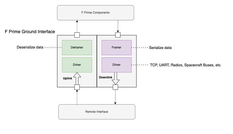
In the most basic form, the F´ ground system pattern consists of two sides: uplink and downlink. These two sides each have two layers: framing and driver. Uplink handles data coming from the remote side of the interface, downlink handles data going to the remote interface, framing handles serializing and deserializing data to and from byte buffers, and the driver layer handles writing data to and from the hardware.
Also of note is the framing protocol, which breaks out the handling of the byte serialization for quick adaptation. Each of these stages need to allocate memory and thus users should also consult the buffer management guide.
Note: in this guide we will refer to the driver layer but many projects will refer to it as the radio or communication layer. The function of this layer is to read and write bytes to some hardware and the nature of that hardware is irrelevant as long as it can send and receive bytes.
Ground Interface Architecture
Standard F´ components handle two types of data: com buffers and raw buffers. Com buffers transmit standard F´ items
(e.g. events, telemetry, and commands) whereas raw buffers (Fw::Buffer) transmit any raw bytes like file data. Thus
the F´ ground interface must handle both types of data. Communications hardware typically only transmits bytes of data
and knows nothing about the nature of that data. The goal of the ground interfaces is to ensure that the various types
of F´ data can be translated into a sequence of bytes that can be reconstructed on the other side of the interface. This
architecture is described below.
Driver
Drivers manage hardware communications. These can be simple hardware interfaces (e.g. TCP or UART) or far more complex constructs (e.g. radios, spacecraft buses). From the perspective of F´, the driver has two functions: provide incoming data and handle outgoing data.
Note: typically projects use a single driver to handle both input and output, however; two drivers may be used to if differing behavior is needed for uplink and downlink.(e.g. UDP downlink for speed and Tcp uplink reliability).
All drivers implement an input port receiving data from the framer. The driver should write input data to the hardware the driver manages. Drivers implement at least one of two methods to retrieve data from hardware: an input port to poll for available data and an output read port for asynchronous data, which often is supported by a read thread. Generic drivers implement both such that they can be used in a threaded context or rate group-driven polling context. The driver is responsible for reading the data from the hardware in either context.
Note: the F´ uplink layer is compatible with both polling and receiving drivers as described in Uplink below.
Sending Data
To send data to a driver, an Fw::Buffer is passed to the driver’s send input port and the data wrapped by the buffer
will be pushed out to the hardware. Drivers respond to sends with one of the following statuses:
- SendStatus.SEND_OK: indicates the send was successful
- SendStatus.SEND_RETRY: indicates subsequent retransmission will likely succeed
- SendStatus.SEND_ERROR: send failed, the data was not sent, and future success cannot be predicted
Polling Data
Polling for data allows the system to determine when to look for available data. This often means the driver does not
need a thread constantly trying to read data. It is used in rate-group-driven baremetal systems to schedule the
reception of data and remove the need for a task to spin looking for data. To poll data, an Fw::Buffer is passed to
the driver’s poll input port where the buffer is filled with available data. Polling returns the following statuses:
- PollStatus.POLL_OK: indicates the buffer is filled with valid data
- PollStatus.POLL_RETRY: indicates a subsequent retry of the polling call will likely result in valid data
- PollStatus.POLL_ERROR: polling failed, the buffer data is invalid, and future success cannot be predicted
Receiving Data
Receiving data is to handle asynchronous input of data without the need to poll for it. This typically means the driver
has an internal task that calls the receive output port when data has been received. Receive ports are passed
Fw::Buffers and a receive status as described below. Receive RETRY status is not used as the external system has
nothing to retry.
- RecvStatus.RECV_OK: receive works as expected and the buffer has valid data
- RecvStatus.RECV_ERROR: receive failed and the buffer does not have valid data
Uplink
Uplink handles received data, unpacks F´ data types, and routes these to the greater F´ system. In a typical formation, these com buffers are sent to the command dispatcher and raw buffers are sent to the file uplink. Uplink is implemented with the Svc.Deframer component. This component may be rate group driven in which case it polls for data or it may be driven by a driver’s receive output port in which case it handles the data on that incoming port call. Svc.Deframer implements the DeframingProtocolInterface.
Svc.Deframer unpacks F´ data from the supplied buffer using a Svc::DeframingProtocol, which calls back through the DeframingProtocolInterface to send deframed packets out to F´ components.
Internally, Svc.Deframer uses a circular buffer to store incoming data such that messages are not required to be complete. This buffer is updated with the latest data and then processed for messages on each poll or receiving of data.
Downlink
Downlink takes in F´ data and wraps the data with bytes supporting the necessary protocol. This assembled data is then sent to the driver for handling. Downlink is implemented with the Svc.Framer component, which implements the FramingProtocolInterface.
Svc.Framer packs F´ data using a Svc::FramingProtocol, which calls back through the FramingProtocolInterface to send framed packets out to the driver.
Adding a Custom Wire Protocol
To add a custom wire protocol an implementation needs to be written for two interfaces (virtual base classes). These are Svc::FramingProtocol and Svc::DeframingProtocol.
Svc::FramingProtocol implementors need to implement one function: frame, taking in a pointer to the data to frame, the
size of the data, and a packet type for the data. The base class supplies a
FramingProtocolInterface member variable, m_interface, that
allows implementors to call out for allocating data and sending the newly framed data. A minimal implementation is:
class MyFrameProtocol : public Svc::FramingProtocol {
  public:
    MyFrameProtocol() {}

    void frame(const U8 *const data, const U32 size, Fw::ComPacket::ComPacketType packet_type) {
        Fw::Buffer my_framed_data = m_interface.allocate(size);
        my_framed_data.getSerializeRepr().serialize(0xdeadbeef); // Some start word
        my_framed_data.getSerializeRepr().serialize(size);       // Write size
        my_framed_data.getSerializeRepr().serialize(data, size, true); // Data copied to buffer no length included
        m_interface.send(my_framed_data);
    }
};
Here the protocol starts a frame with 0xdeadbeef, followed by the data size, and then the data.
Svc::DeframingProtocol implementors need to implement one function: deframe, taking in a circular buffer supplying data,
filling the needed variable, and returning a status. The base class supplies a
DeframingProtocolInterface member variable, m_interface,
that allows implementors to call out for allocating data and routing the deframed data. A minimal implementation is:
class MyDeframeProtocol : public DeframingProtocol {
  public:
    MyDeframeProtocol() {}

    DeframingProtocol::DeframingStatus deframe(Types::CircularBuffer& ring, U32& needed) {
        U32 start = 0;
        U32 size = 0;
        // Check for header or ask for more data
        if (ring.get_remaining_size() < 8) {
            needed = 8;
            return DeframingProtocol::DEFRAMING_MORE_NEEDED;
        }
        // Peek into the header and read out values
        (void) ring.peek(start, 0);
        (void) ring.peek(size, 0);
        needed = 4 + 4 + size; // start + size + data

        // Not enough data, call out for more
        if (ring.get_remaining_size() < size) {
            return DeframingProtocol::DEFRAMING_MORE_NEEDED;
        }
        // Protocol violation
         else if (start != 0xdeadbeef) {
            return DeframingProtocol::DEFRAMING_INVALID_CHECKSUM;
        }
        Fw::Buffer buffer = m_interface->allocate(size);
        buffer.setSize(size);
        ring.peek(buffer.getData(), size, 8);
        m_interface->route(buffer);
        return DeframingProtocol::DEFRAMING_STATUS_SUCCESS;
    }
Here the protocol starts a frame with 0xdeadbeef and uses size to extra the data. Deframing is typically the inverse
of the framing protocol as seen in this example.
Note: implementors should always use peak to get data and never rotate it, as Svc.Deframer will rotate the buffer
based on the status.
Adding a Custom Driver
To be compatible with this ground interface, a driver must implement the byte steam model interface. The driver may add any other ports, events, telemetry, or other F´ constructs as needed but it must define the ports as described in the ByteStreamDriverModel. These ports are called out in the below FPP snippet.
    output port ready: Drv.ByteStreamReady
    guarded input port send: Drv.ByteStreamSend

    output port $recv: Drv.ByteStreamRecv
    guarded input port poll: Drv.ByteStreamPoll
- ready: (output) drivers call this port without arguments to signal it is ready to receive data via the send port.
- send: (input) clients call this port passing in an
Fw::Bufferto send data. - recv: (output) drivers operating in asynchronous mode call this port with a RecvStatus and
Fw::Bufferto provide data. - poll: (input) drivers operating in poll mode fill an
Fw::Bufferand return a PollStatus to provide data.